General Machining Guidelines for Turning Operations
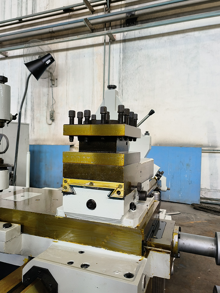
Tool Clamping
- The length of the tool shank extending from the tool holder should not exceed 1.5 times the height of the tool shank (except for boring, grooving, etc.).
- The tool shank axis should be perpendicular or parallel to the feed direction.
- Adjustment of Tool Tip Height:
- For turning end faces, conical surfaces, threads, forming turning, cutting solid workpieces, etc., the tool tip is generally aligned with the workpiece axis.
- For rough turning of outer diameters and fine boring, the tool tip is generally slightly above the workpiece centerline.
- For fine turning of long shafts, rough boring, cutting hollow workpieces, etc., the tool tip is generally slightly below the workpiece centerline.
- The bisector of the thread cutting tool’s cutting edge should be perpendicular to the workpiece axis.
- When clamping the tool, the spacer under the tool shank should be minimal and flat, and the clamping screws should be tightened securely.
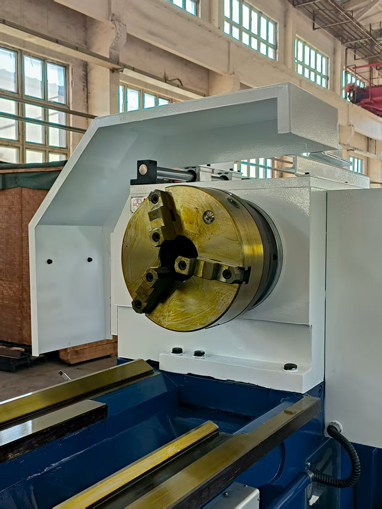
Workpiece Clamping
- When using a three-jaw chuck to clamp a workpiece for rough or finish turning, if the workpiece diameter is less than or equal to 30mm, the overhang should be less than 5 times the diameter; if the workpiece diameter is greater than 30mm, the overhang should be less than 3 times the diameter.
- When clamping irregularly weighted workpieces using a four-jaw chuck, faceplate, angle iron (bent plate), etc., counterweights must be added.
- When machining shaft parts between centers, adjust the tailstock center to align with the lathe spindle axis before turning.
- When machining long workpieces between centers, a follower rest or center rest should be used. During the process, adjust the pressure on the center and lubricate the dead center and center rest.
- When using a tailstock, the sleeve should extend as little as possible to reduce vibration.
- When clamping workpieces with a small supporting surface and high height on a vertical lathe, high chuck jaws should be used, and support rods or pressure plates should be added to secure the workpiece.
- When turning wheel-type or sleeve-type castings or forgings, align them based on the unprocessed surface to ensure even wall thickness after machining.
Turning Operations
- When turning stepped shafts, to ensure rigidity, start with the larger diameter parts and then proceed to the smaller diameter parts.
- When cutting grooves on shaft parts, perform the cutting before finish turning to prevent deformation of the workpiece.
- For finish turning shafts with threads, generally finish the threaded part first and then finish the non-threaded portion.
- Before drilling, ensure the workpiece end face is turned flat, and if necessary, first drill a center hole.
- When drilling deep holes, first drill a pilot hole.
- For turning holes of diameter φ10–φ20mm, the tool shank diameter should be 0.6–0.7 times the hole diameter; for holes larger than φ20mm, a tool holder-mounted tool shank is generally used.
- When turning multi-start threads or multi-start worms, perform test cutting after adjusting the gear train.
- When using an automatic lathe, adjust the tool and workpiece relative position according to the machine’s adjustment card, perform test turning, and proceed with production once the first piece is qualified; during processing, always monitor tool wear and workpiece dimensions and surface roughness.
- On a vertical lathe, after adjusting the tool post, the crossbeam should not be moved arbitrarily.
- When the workpiece has positional tolerance requirements for certain surfaces, try to complete the turning operation in a single clamping.
- When turning cylindrical gear blanks, the hole and reference end face must be machined in one clamping. If necessary, mark the gear pitch circle near the reference end face.