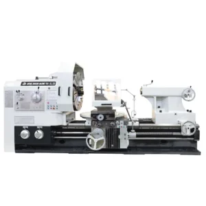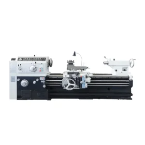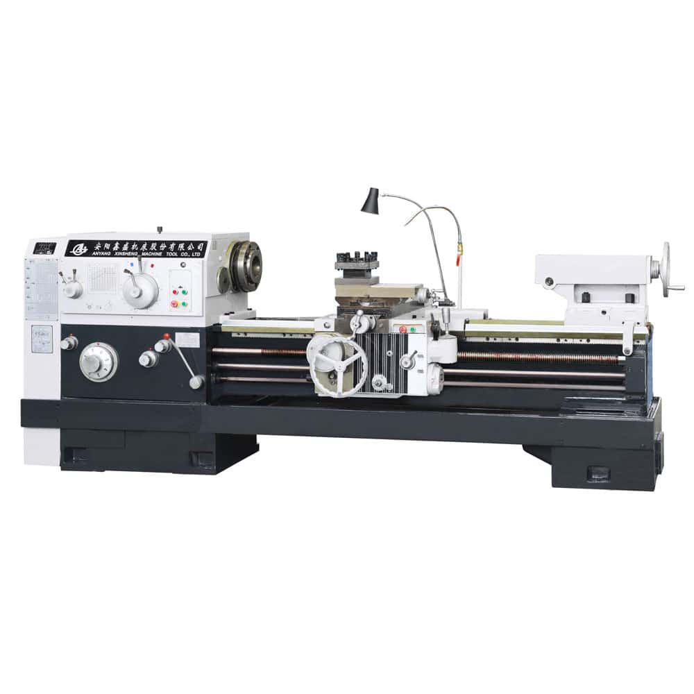
CW6163B/6180B/6194B Conventional Horizontal Lathe
Maximum swing over bed: Ø630 mm to Ø940 mm
Maximum processing length:9850 mm
Swing over gap:830/1000/1140 mm
Pan of guideway:550mm
Description
1.1 Main Purpose
This series of lathes is suitable for a wide range of turning operations, such as machining internal and external cylindrical surfaces, conical surfaces, various rotary surfaces, and end faces. It can also be used for cutting various standard threads — including metric, inch, module, and diametral pitch threads — as well as for drilling, reaming, tapping, and broaching keyways.
1.2 Machining Accuracy of Workpieces
When performing a finish turning test, the roundness error of the test piece shall not exceed 0.01 mm (or 0.02 mm when the maximum swing over bed exceeds Ø800 mm).
The cylindricity error, measured over a length of 300 mm, shall not exceed 0.04 mm.
The surface roughness (Ra) shall not exceed 2.5 μm.
1.3 Main Structural Features
- (1) The machine bed adopts a high torsional-rigidity horizontal structure, manufactured from high-grade cast iron with induction-hardened and precision-ground guideways. The bed width is 550 mm.
- (2) The guideway pair, lined with PTFE (polytetrafluoroethylene) anti-friction soft strips, provides excellent wear resistance, vibration damping, and long-term accuracy retention.
- (3) The spindle employs a three-support structure, ensuring high rigidity and high precision, suitable for heavy-duty cutting. The spindle through-hole diameter is Ø100 mm.
- (4) The machine offers 18 spindle speed steps over a wide range, enabling optimal speed selection for different machining requirements.
- (5) Both metric and inch threads can be cut directly without the need for gear changes.
- (6) The carriage gearbox is equipped with a rapid traverse mechanism for convenient operation.
1.4 Machine Model Designation

Parameter
| ITEM | UNIT | CW6163B/CW6263B | CW6180B/CW6280B | CW6194B/CW6294B |
| CAPACITIES | ||||
| Swing over bed | mm | 630 | 800 | 940 |
| Swing over carriage | mm | 350 | 520 | 660 |
| Max.length of workpiece | mm | 750 1000 1500 2000 3000 4000 5000 6000 8000 10000 | ||
| Max.turning length | mm | 600 850 1350 1850 2850 3850 4850 5850 7850 9850 | ||
| Swing over gap | mm | 830 | 1000 | 1140 |
| Effective widthof gap | mm | 300 | ||
| Pan of guideway | mm | 550 | ||
| SPINDLE | ||||
| Spindle nose | C11 | |||
| Spindle bore | mm | 100 | ||
| Taper hole of spindle | 1:20/120 | |||
| Range of spindle speeds | r/min | 7.5~1000 | 6~800 | 6~800 |
| No.of spindle speeds | 18 | |||
| FEED | ||||
| Longitudinal and cross | r/min | 64;0.1~24.32 | ||
| Cross/long longitudinal feed | 1/2 | |||
| Screw pitch of leadscrew | mm | 12 | ||
| No. and range of metric thread | mm | 50;1~240 | ||
| No. and range of inch thread | 26;14~1 | |||
| No. and range of module thread | mm | 53;0.5~120 | ||
| No. and range of dia. thread | 24;28~1 | |||
| Rapid traverse speed | mm/min | 4000 | ||
| TURRET | ||||
| Max.travel of cross slide | mm | 440 | 540 | 570 |
| Max.travel of top slide | mm | 200 | ||
| Section of tool shank | mm | 32(192×192) | ||
| TAILSTOCK | ||||
| Dia. of tailstock | mm | 100 | ||
| Travel of tailstock quill | mm | 250 | ||
| Taper hole of tailstock quill | mores 5 | |||
| OTHERS | ||||
| Main motor power | kw | 11 | ||
| Length | mm | 2958 3275 3725 4225 5225 6275 7355 8355 10275 12275 | ||
| Width | mm | 1393 | 1473 | 1430 |
| Height | mm | 1537 | 1622 | 1690 |
Video
FAQ
1.Lifting and Transportation Instructions
When lifting a machine tool packed in a wooden crate, the wire ropes must be attached according to the markings indicated on the outside of the crate. During lifting, moving, and lowering, the bottom and sides of the crate must not be subjected to impact or excessive vibration to avoid affecting the accuracy of the machine tool.
When lifting the machine tool itself, for machines of specifications Ф630×750—3000, two Ф50×1000 steel bars should be used; for machines of specifications Ф630×4000 and above, two Ф80×1000 steel bars should be used. These bars should be inserted into the holes at both ends of the machine bed, and the wire ropes should be hooked onto both ends of the steel bars. Make sure that the wire ropes cannot slip off.
Where the wire ropes may come into contact with the machine tool, wooden blocks or cotton yarn should be placed as padding to prevent scratches or damage. When lifting, the carriage may be repositioned to ensure proper balance of the machine tool.
2. What is the maximum machining diameter of the lathe?
The maximum machining diameter (swing over saddle recess) is Ø1140 mm, depending on the model.
Typical maximum swing over bed ranges from Ø630 mm to Ø940 mm.
3. What is the maximum machining length?
The maximum machining length depends on the selected machine configuration.
For the CW61 series, the maximum processing length can reach 11850 mm.