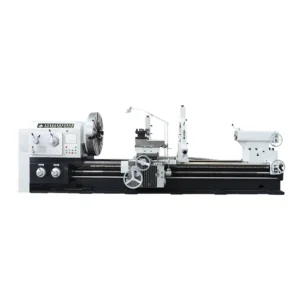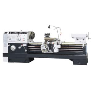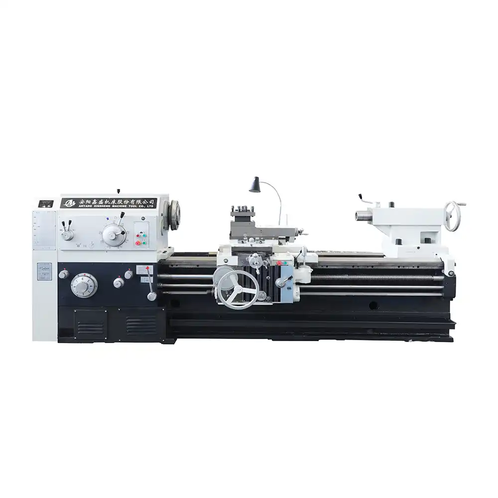
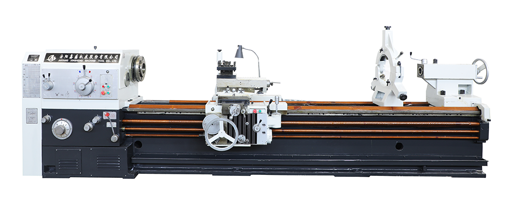
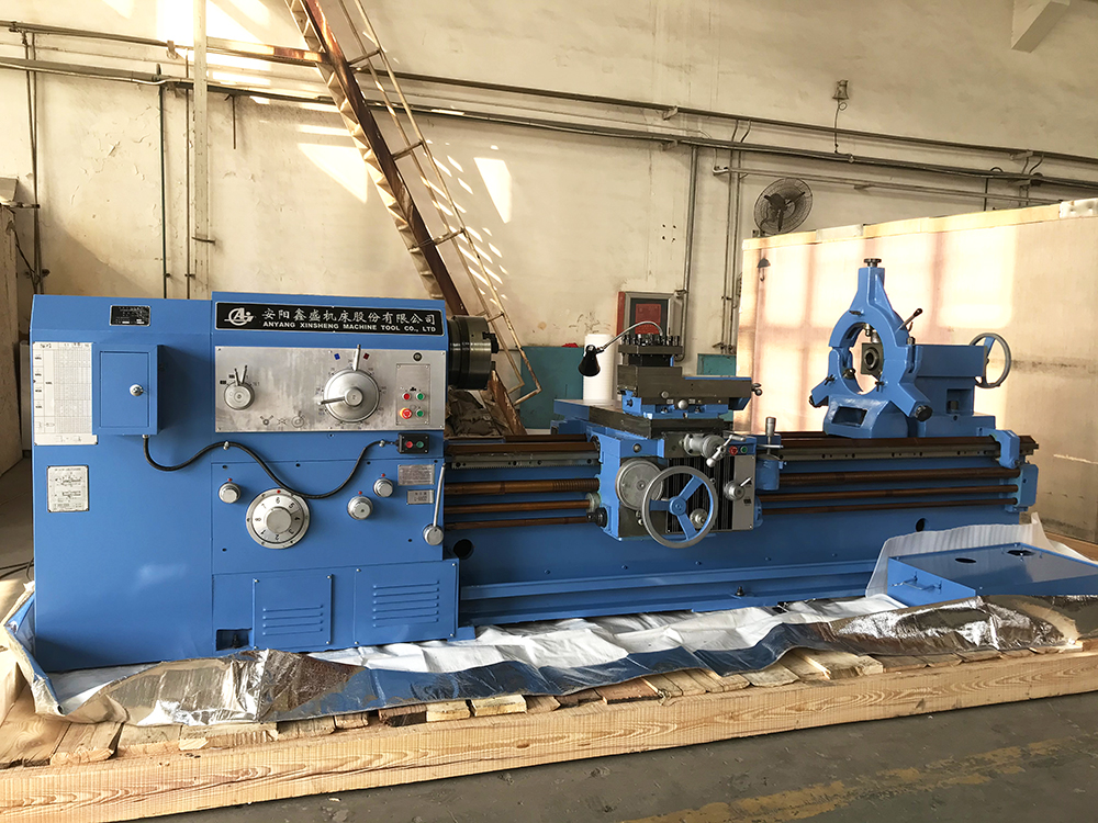
CW6180/61100 Standard Series Lathes
Maximum swing over bed: Ø800 mm / Ø1000 mm
Max. swing over carriage:Ø480 / Ø680 mm
Maximum processing length:7850 mm
Pan of guideway:600mm
Description
1.1 Main Applications:
This series of lathes is suitable for various turning operations, such as turning inner and outer cylindrical surfaces, conical surfaces, other surfaces of revolution, end faces, and can also process various common threads—such as metric, inch, module, and diametral pitch threads, as well as drilling, reaming, tapping, and broaching keyways. This machine tool can process materials such as steel, cast iron, and non-ferrous metals.
1.2 Machining Accuracy and Specifications of Parts
When the machine tool performs finish turning of test pieces, the roundness error shall not exceed 0.01mm, and the cylindricity error shall not exceed 0.04mm over a measurement length of 300mm; the surface roughness (Ra) shall not exceed 2.5μm.
1.3 Main Structural Features
(1) High torsional rigidity horizontal flat bed, manufactured from high-quality cast iron with meticulous care, with guideway surfaces subjected to induction hardening and precision treatment; bed surface width is 600mm;
(2) Guideway pairs composed of guideways bonded with polytetrafluoroethylene (PTFE) guide strips are wear-resistant, vibration-absorbing, and have good accuracy retention;
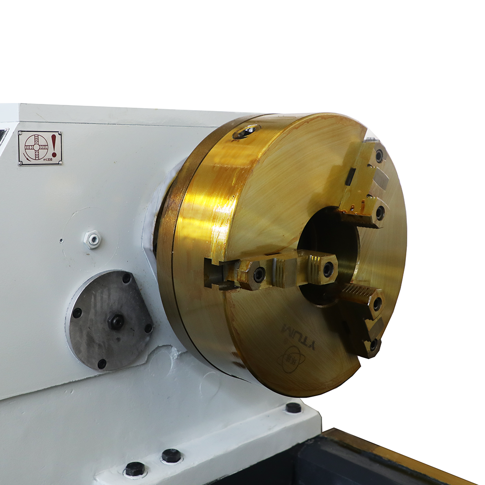
(3) The spindle adopts a three-support structure, with high rigidity and high precision, capable of heavy-duty cutting. The spindle through-hole is a large-diameter bore of Ф100mm;
(4) 18-speed wide speed regulation range, allowing selection of relatively optimal rotational speeds;
(5) Capable of directly turning metric and inch threads;
(6) The apron is equipped with a rapid traverse mechanism.
1.4 Machine Model Designation

Parameter:
| ITEM | UNIT | CW6180 | CW61100 |
| CAPACITIES | |||
| Swing over bed | mm | 800 | 1000 |
| Swing over carriage | mm | 480 | 680 |
| Max.length of workpiece | mm | 1500 2000 3000 4000 5000 6000 | |
| Max.turning length | mm | 1350 1850 2850 3850 4850 5850 | |
| Pan of guideway | mm | 600 | |
| SPINDLE | |||
| Spindle nose | mm | C11(C15 optional) | |
| Spindle bore | mm | 100(140 optional) | |
| Taper hole of spindle | 1:20 | ||
| Range of spindle speeds | r/min | forward:6~750 reverse:10~775 | |
| No.of spindle speeds | 18/6 | ||
| FEED | |||
| Longitudinal and cross | 64;0.1~24.32 | ||
| Cross/long longitudinal feed | 1/2 | ||
| Screw pitch of leadscrew | mm | 12 | |
| No. and range of metric thread | 50 ;1~240 | ||
| No. and range of inch thread | 26 ;14~1 | ||
| No. and range of module thread | 53 ;0.5~120 | ||
| No. and range of dia. thread | 24 ;28~1 | ||
| Rapid traverse speed | mm/min | 4000 | |
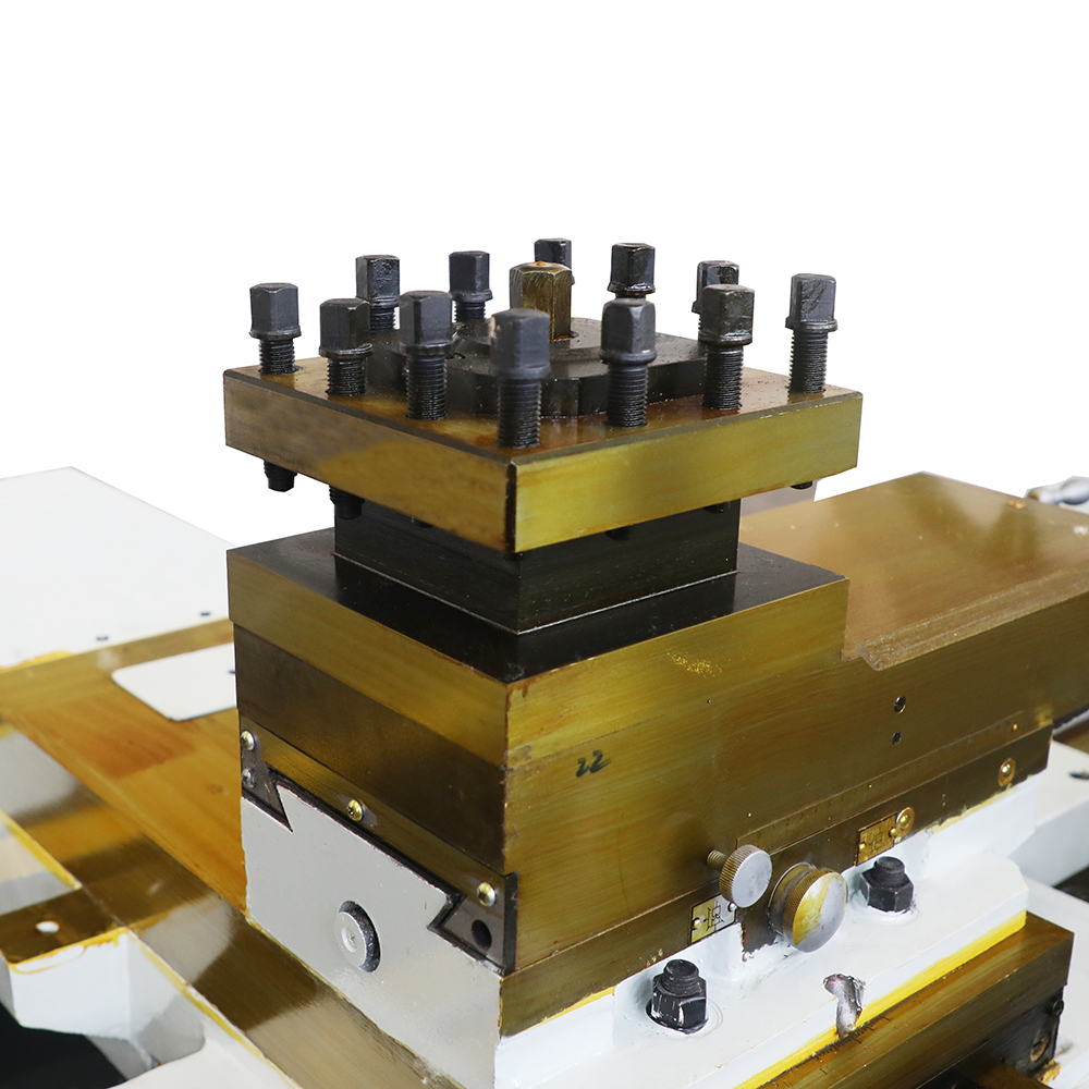
| TURRET | |||
| Distance of spindle and tool plane | mm | 33 | |
| Tool post swing range | ° | ±90° | |
| Max.travel of cross slide | mm | 500 | |
| Max.travel of top slide | mm | 200 | |
| Section of tool shank | mm | 32(202×202) | |
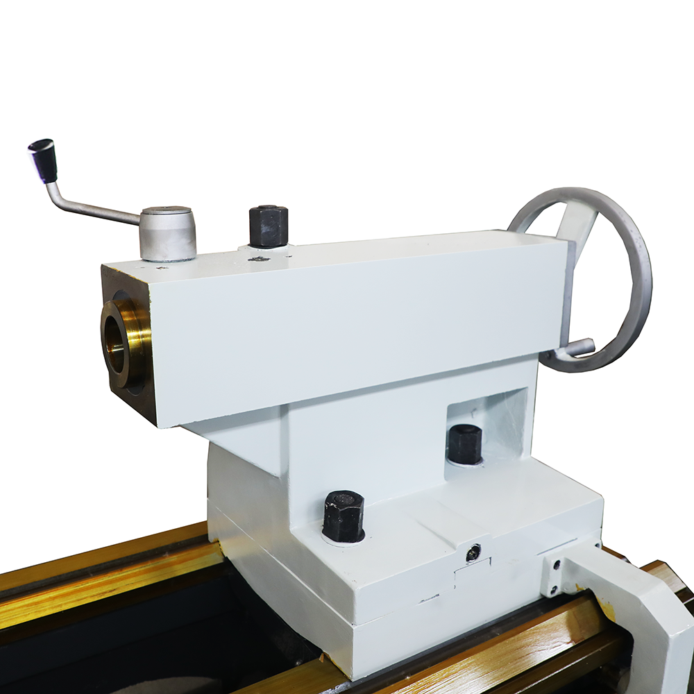
| TAILSTOCK | |||
| Dia. of tailstock | mm | 100 | |
| Travel of tailstock quill | mm | 250 | |
| Taper hole of tailstock quill | morse6 | ||
| OTHERS | |||
| Main motor power | kw | 11 | |
| Length | mm | 3670 3985 5165 6220 7400 8260 | |
| Width | mm | 1730 | |
| Height | mm | 1450 | |
Video
FAQ
1.Machine Tool Handling
When hoisting and transporting the machine tool with packing case, the wire ropes shall be installed in accordance with the markings on the outside of the case. During moving and lowering, the bottom and sides of the case shall not be subjected to impact or excessive vibration. Under no circumstances shall the packing case be excessively tilted, so as not to affect the accuracy of the machine tool.
2.Installation
For installing the machine tool, a level location shall be selected first. Then, determine the installation space according to the specified environmental requirements and foundation drawing, and prepare the foundation. When arranging multiple machine tools, the space required for operation and maintenance shall be considered, leaving at least 1 meter of space outside the maximum contour of the machine tool. To ensure that the machine tool can work stably, the foundation must have sufficient depth, and the specific dimensions shall be determined by the user according to the local soil conditions.