Description
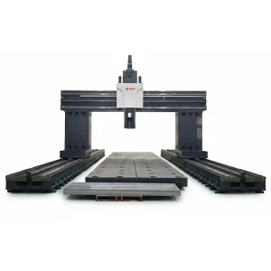
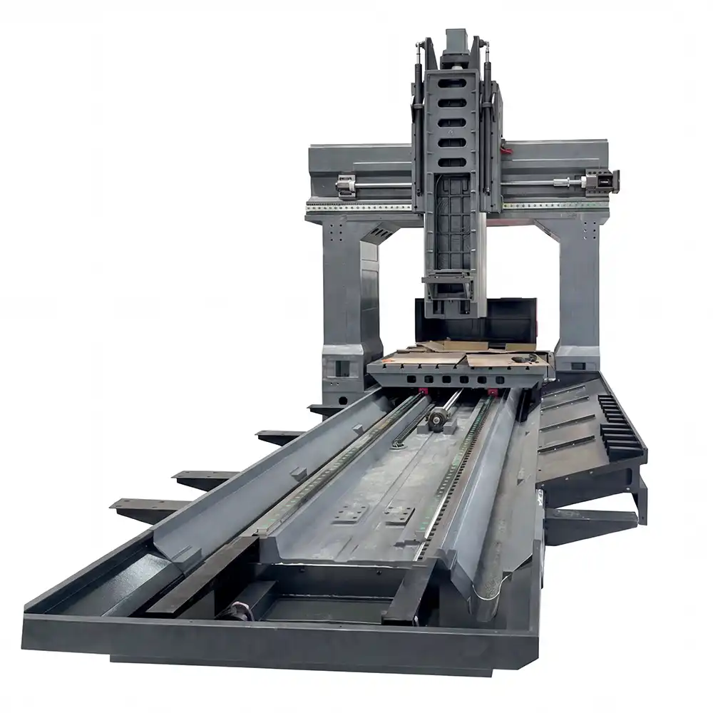
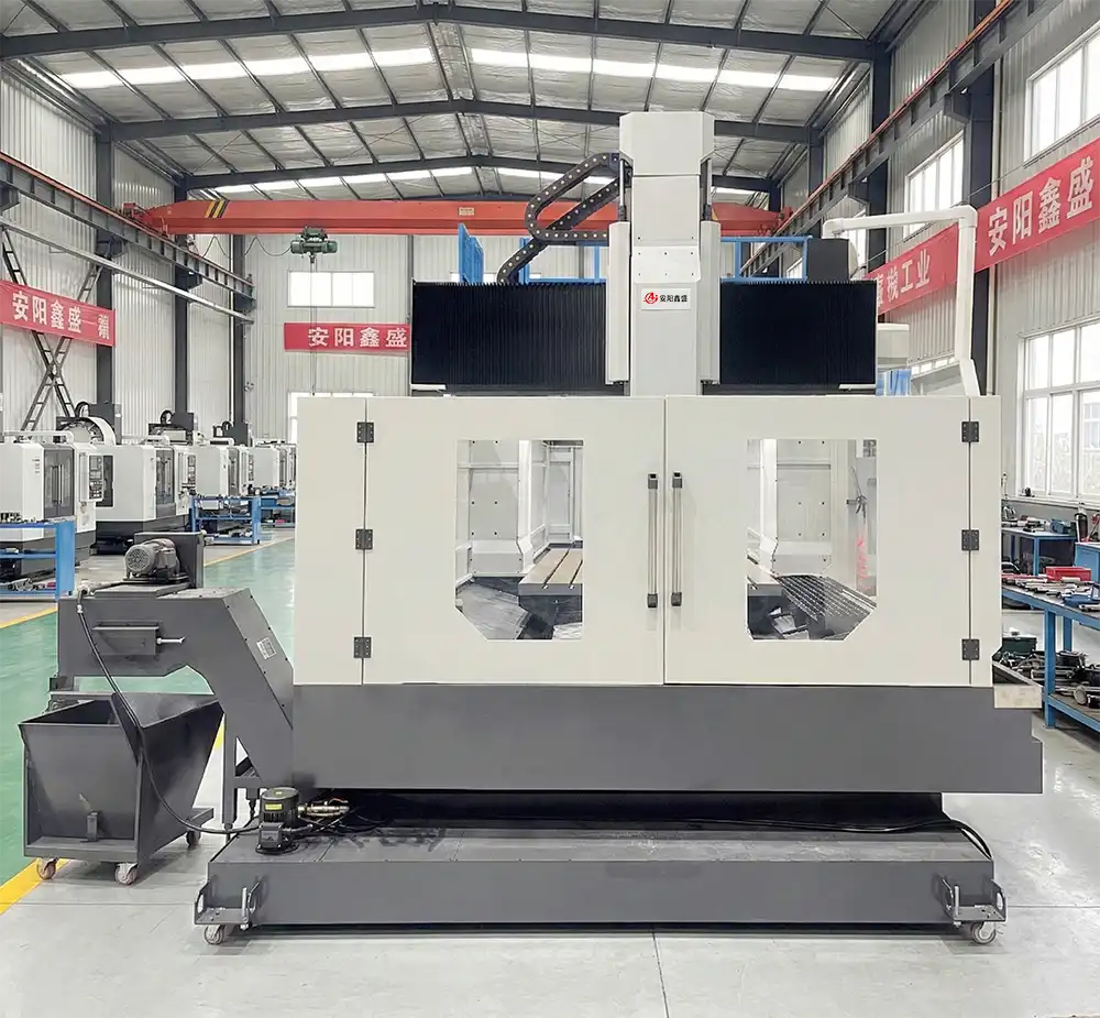
The columns and crossbeam adopt an integrally cast structural design, and all critical mating surfaces are precision hand-scraped to ensure excellent assembly accuracy, structural rigidity, and well-balanced load distribution of the entire machine; the worktable features a rear-enclosed double-layer structural design, significantly enhancing overall rigidity and cutting resistance, with the maximum load capacity increased by approximately 30%; meanwhile, a modular spindle design is provided, allowing flexible configuration according to different machining requirements and delivering a wide range of cutting performance to fully meet high-precision and high-efficiency machining applications.
Parameter:
Model:2016/2518/3020/3028/4028/6028/8028
| Item | Unit | 2016 | 2518 | 3020 | 3028 | 4028 | 6028 | 8028 |
| Machining Range | ||||||||
| X-axis Travel | mm | 2000 | 2500 | 3000 | 3000 | 4000 | 6000 | 8000 |
| Y-axis Travel | mm | 1600 | 1800 | 2000 | 2800 | |||
| Z-axis Travel | mm | 850 | 850 | 850 | 1000/1250 | |||
| Gantry Passage Width | mm | 1600 | 1800 | 2100 | 2800 | |||
| Distance from Spindle Nose to Work Table | mm | 150-1000 | 200-1050 | 150-1000 | 200-1200/1450 | |||
| Work Table | ||||||||
| Work Table Size | mm | 2200×1400 | 2500×1600 | 3000×1800 | 3000×2100 | 4000×2100 | 6000×2100 | 8000×2100 |
| Work Table Load Capacity | t | 3.5 | 7 | 8 | 10 | 16 | 20 | 25 |
| T-slot Specification (Width x Spacing x Number) | mm | 22x190x7 | 22x180x9 | 22x190x9 | 28x220x9 | 28x220x9 | 28x220x9 | 28x220x9 |
| Drive Feed | ||||||||
| Max. Cutting Speed X/Y/Z | m/min | 10/10/10 | ||||||
| Rapid Traverse Speed X/Y/Z | m/min | 12/15/15 | ||||||
| Spindle | ||||||||
| Max. Spindle Speed | r/min | 6000 | 6000/3500 | 6000/3500 | 6000/3500 | 6000/3500 | ||
| Spindle Rated Power | kW | 15 | 22 | 22 | 22 | 22 | ||
| Spindle Rated Torque | N.m | 143 | Rectangular Guide 140 Square Ram 700 | |||||
| Spindle Taper | – | BT50 | ||||||
| Ram Cross-section | mm | Rectangular Guide | Rectangular Guide or 400×400 Square Ram | |||||
| Tool Magazine (Optional) | ||||||||
| Tool Magazine Capacity | T | 24/32/40/60/120 | ||||||
| Tool Shank Type | – | BT50 | ||||||
| Max. Tool Diameter (Full/No Adjacent) | mm | Φ125/Φ250 | ||||||
| Max. Tool Length | mm | 400 | ||||||
| Max. Tool Weight | kg | 25 | ||||||
| Accuracy (Executive Standard GB/19362.1-2003) | ||||||||
| Positioning Accuracy X/Y/Z | mm | 0.012/ 0.014/ 0.012 |
0.016/ 0.015/ 0.012 |
0.020/ 0.016/ 0.012 |
0.020/ 0.025/ 0.016 |
0.025/ 0.025/ 0.016 |
0.035/ 0.025/ 0.016 |
0.045/ 0.025/ 0.016 |
| Repeatability Positioning Accuracy X/Y/Z | mm | 0.008/ 0.009/ 0.009 |
0.010/ 0.010/ 0.009 |
0.012/ 0.011/ 0.009 |
0.012/ 0.016/ 0.010 |
0.016/ 0.016/ 0.010 |
0.020/ 0.015/ 0.010 |
0.024/ 0.015/ 0.010 |
| Others | ||||||||
| Total Power Capacity | KVA | 40 | 40 | 40 | 50 | 50 | 50 | 50 |
| Machine Weight | t | 14 | 23 | 26 | 34 | 43 | 55 | 68 |
| Machine Overall Dimensions (L x W x H) | mm | 6200x3300x4500 | 6800x3700x4500 | 8500x4000x4500 | 8500x4800x5200 | 11500x4800x5200 | 16000x4800x5200 | 20000x4800x5200 |
Model:4032/6032/8032/4036/6036/8036
| Item | Unit | 4032 | 6032 | 8032 | 4036 | 6036 | 8036 |
| Machining Range | |||||||
| X-axis Travel | mm | 4000 | 6000 | 8000 | 4000 | 6000 | 8000 |
| Y-axis Travel | mm | 3200 | 3600 | ||||
| Z-axis Travel | mm | 1000/1250 | |||||
| Gantry Passage Width | mm | 3200 | 3600 | ||||
| Distance from Spindle Nose to Work Table | mm | 200-1200/1450 | |||||
| Work Table | |||||||
| Work Table Size | mm | 4000×2500 | 6000×2500 | 8000×2500 | 4000×2700 | 6000×2700 | 8000×2700 |
| Work Table Load Capacity | t | 18 | 25 | 30 | 18 | 25 | 30 |
| T-slot Specification (Width x Spacing x Number) | mm | 28x220x11 | 28x220x12 | ||||
| Drive Feed | |||||||
| Max. Cutting Speed X/Y/Z | m/min | 6/6/6 | |||||
| Rapid Traverse Speed X/Y/Z | m/min | 10/10/10 | |||||
| Spindle | |||||||
| Max. Spindle Speed | r/min | 6000 | 6000 | 6000 | 3500 | 3500 | 3500 |
| Spindle Rated Power | kW | 22 | 22 | 22 | 22 | 22 | 22 |
| Spindle Rated Torque | N.m | Rectangular Guide 140 Square Ram 700 | |||||
| Spindle Taper | – | BT50 | BT50 | BT50 | BT50 | BT50 | BT50 |
| Ram Cross-section | mm | Rectangular Guide or 420×420 Square Ram | 450×450 Square Ram | ||||
| Tool Magazine (Optional) | |||||||
| Tool Magazine Capacity | T | 24/32/40/60/120 | |||||
| Tool Shank Type | – | BT50 | |||||
| Max. Tool Diameter (Full/No Adjacent) | mm | Φ125/Φ250 | |||||
| Max. Tool Length | mm | 400 | |||||
| Max. Tool Weight | kg | 25 | |||||
| Accuracy (Executive Standard GB/19362.1-2003) | |||||||
| Positioning Accuracy X/Y/Z | mm | 0.025/ 0.025/ 0.016 |
0.035/ 0.025/ 0.016 |
0.045/ 0.025/ 0.016 |
0.025/ 0.032/ 0.016 |
0.035/ 0.032/ 0.016 |
0.045/ 0.032/ 0.016 |
| Repeatability Positioning Accuracy X/Y/Z | mm | 0.016/ 0.016/ 0.010 |
0.024/ 0.016/ 0.010 |
0.032/ 0.016/ 0.010 |
0.016/ 0.020/ 0.010 |
0.024/ 0.020/ 0.010 |
0.032/ 0.020/ 0.010 |
| Others | |||||||
| Total Power Capacity | KVA | 65 | |||||
| Machine Weight | t | 48 | 60 | 72 | 50 | 62 | 76 |
| Machine Overall Dimensions (L x W x H) | mm | 11000x6200x5200 | 16000x6200x5200 | 20000x6200x5200 | 11000x6600x5200 | 16000x6600x5200 | 18000x6600x5200 |
Model:6042/6032/10042/8045/10045/12045
| Item | Unit | 6042 | 8042 | 10042 | 8045 | 10045 | 12045 |
| Machining Range | |||||||
| X-axis Travel | mm | 6000 | 8000 | 10000 | 8000 | 10000 | 12000 |
| Y-axis Travel | mm | 4200 | 4200 | 4200 | 4500 | 4500 | 4500 |
| Z-axis Travel | mm | 1250/1500 | |||||
| Gantry Passage Width | mm | 4200 | 4200 | 4200 | 4500 | 4500 | 4500 |
| Distance from Spindle Nose to Work Table | mm | 200-1450/1700 | 200-1450/1700 | 200-1450/1700 | 200-1450/1700 | 200-1450/1700 | 200-1450/1700 |
| Work Table | |||||||
| Work Table Size | mm | 6000×3000 | 8000×3000 | 10000×3000 | 8000×3200 | 10000×3200 | 12000×3200 |
| Work Table Load Capacity | t | 31 | 35 | 41 | 37 | 43 | 51 |
| T-slot Specification (Width x Spacing x Number) | mm | 28x220x13 | 28x220x13 | 28x220x13 | 28x220x14 | 28x220x14 | 28x220x14 |
| Drive Feed | |||||||
| Max. Cutting Speed X/Y/Z | m/min | 6/6/6 | |||||
| Rapid Traverse Speed X/Y/Z | m/min | 10/10/10 | |||||
| Spindle | |||||||
| Max. Spindle Speed | r/min | 3500 | |||||
| Spindle Rated Power | kW | 30 | |||||
| Spindle Rated Torque | N.m | 1245 | |||||
| Spindle Taper | – | BT50 | |||||
| Ram Cross-section | mm | 450×450 square machine tool sliding pad or 500×500 square machine tool sliding pad | |||||
| Tool Magazine (Optional) | |||||||
| Tool Magazine Capacity | T | 24/32/40/60/120 | |||||
| Tool Shank Type | – | BT50 | |||||
| Max. Tool Diameter (Full/No Adjacent) | mm | Φ125/Φ250 | |||||
| Max. Tool Length | mm | 400 | |||||
| Max. Tool Weight | kg | 25 | |||||
| Accuracy (Executive Standard GB/19362.1-2003) | |||||||
| Positioning Accuracy X/Y/Z | mm | 0.035/0.028/0.025 | 0.045/0.028/0.025 | 0.055/0.028/0.025 | 0.045/0.030/0.025 | 0.055/0.030/0.025 | 0.065/0.030/0.025 |
| Repeatability Positioning Accuracy X/Y/Z | mm | 0.024/0.022/0.015 | 0.028/0.022/0.015 | 0.036/0.022/0.015 | 0.028/0.023/0.015 | 0.036/0.023/0.015 | 0.044/0.023/0.015 |
| Others | |||||||
| Total Power Capacity | KVA | 65 | |||||
| Machine Weight | t | 80 | 85 | 90 | 92 | 102 | 112 |
| Machine Overall Dimensions (L x W x H) | mm | 16000x8200x5800 | 20000x8200x5800 | 24000x8200x5800 | 20000x9000x5800 | 24000x9000x5800 | 28000x9000x5800 |
Configurations
Configurations for Models 2016 / 2518 / 3020 / 3028 / 4028 / 6028 / 8028 / 4032 / 6032 / 8032
Standard Configurations
-
CNC System
-
Z-axis Hydraulic Balance System
-
Air Gun
-
Pneumatic, Hydraulic, and Centralized Lubrication Systems
-
Local Machine Guarding
-
Internal and External Automatic Chip Conveyor
-
Tool Cooling System
-
Tri-color Signal Lamp, Work Light
-
Standard Accessories and Related Documentation
-
Standard Maintenance Tools
Optional Configurations
-
Z-axis Square Ram (Size: 400×400, 420×420, 450×450)
-
Z-axis Travel 1250mm, Y-axis with 3 Guideways
-
4th / 5th Axis Rotary Table
-
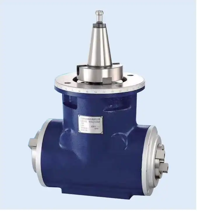
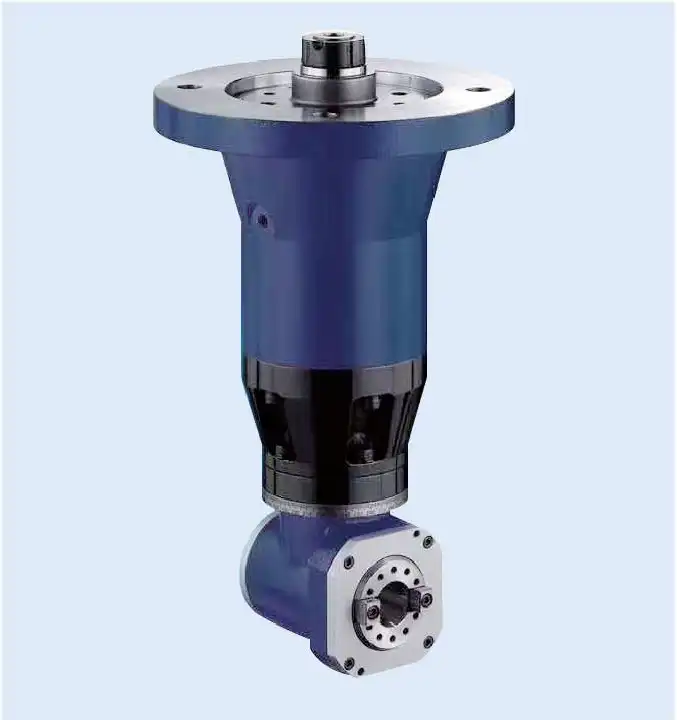
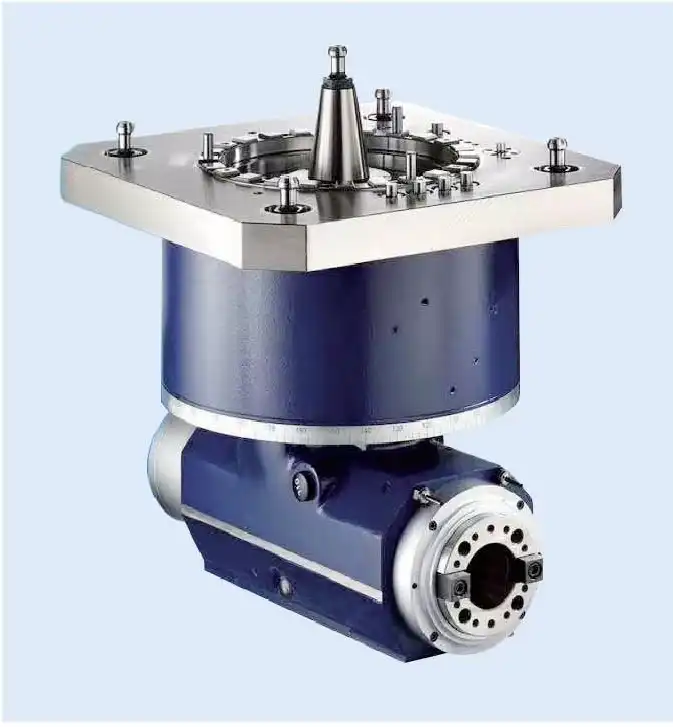
Angle Head (Angular Milling Head)
-
Tool Magazine (ATC)
-
Coolant Through Spindle (CTS)
-
Geared Spindle Box
-
Z-axis Linear Guideway
-
High-speed Spindle
-
3-Axis Full Closed-loop Linear Scales
Configurations for Models 4036 / 6036 / 8036 / 6042 / 8042 / 10042 / 8045 / 10045 / 12045
Standard Configurations
-
CNC System
-
Z-axis Hydraulic Balance System
-
Z-axis Square Ram
-
Geared Spindle Box
-
Air Gun
-
Pneumatic, Hydraulic, and Centralized Lubrication Systems
-
Local Machine Guarding
-
Internal and External Automatic Chip Conveyor
-
Tool Cooling System
-
Tri-color Signal Lamp, Work Light
-
Standard Accessories and Related Documentation
-
Standard Maintenance Tools
Optional Configurations
-
4th / 5th Axis Rotary Table
-
Angle Head (Angular Milling Head)
-
Tool Magazine (ATC)
-
Coolant Through Spindle (CTS)
-
Z-axis with 4 Linear Guideways
-
High-speed Spindle
-
3-Axis Full Closed-loop Linear Scales