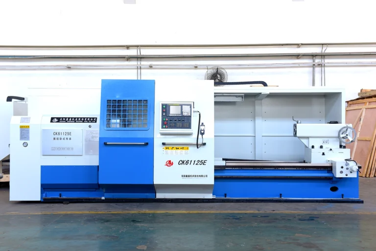
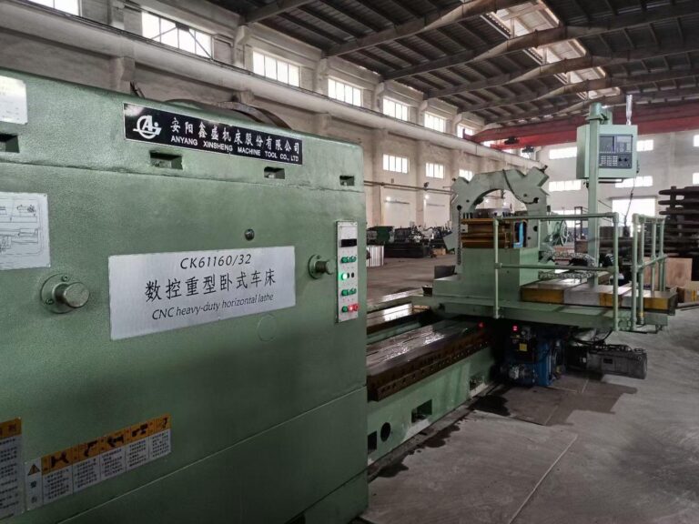
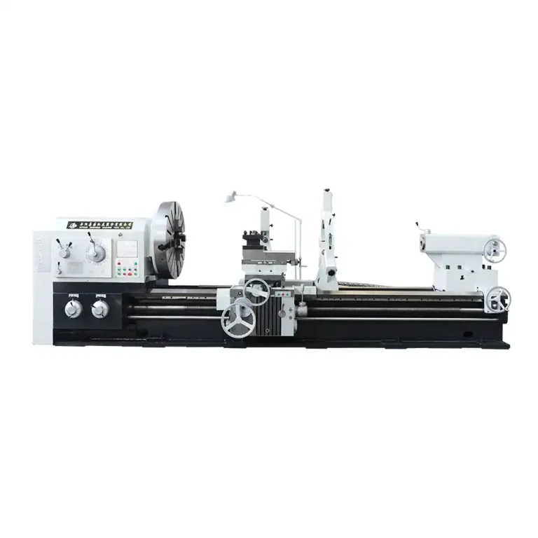
The main structure of the lathe
Introduction to Main Lathe Components
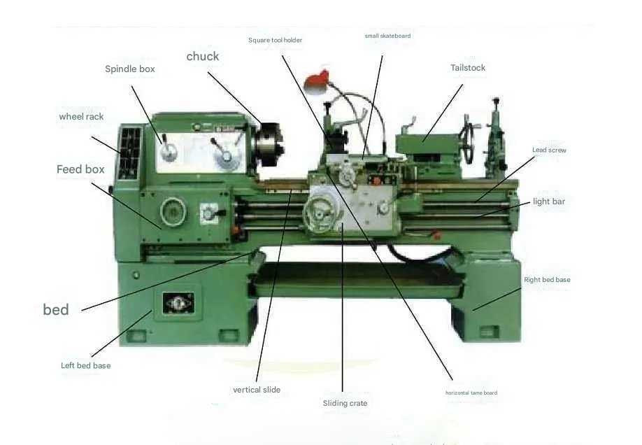
- Feed Box: Uses its internal gear transmission mechanism and external operating handles to transmit the rotational motion of the main spindle to the lead screw or feed rod, providing them with various speeds.
- Change Gear Box: Transmits the rotational motion of the headstock spindle to the feed box. The gears inside can be changed according to the specifications on the feed box’s nameplate and are generally referred to as change gears.
- Headstock: Used to rotate the lathe’s main spindle and the chuck mounted on it. The various handles on the headstock are used to change the spindle speed, with the leftmost handle transmitting the spindle’s motion to the feed box, apron, and other parts.
- Chuck: Used to clamp the workpiece and rotate it along with the spindle. The chuck is removable so other chucks or faceplates can be used.
- Cutting Fluid System: Used to store cutting fluid.
- Work Light: Used for illumination.
- Tool Post: Used to mount the cutting tool. The tool post can hold up to four tools and allows you to quickly change and position them as needed.
- Apron: Mounted on the lathe bed and connected to the carriage. It transmits the rotational motion of the lead screw or feed rod, allowing the carriage and the tool mounted on it to move longitudinally or transversally. The apron contains the cross slide and compound rest. The cross slide enables the tool to move transversally. The compound rest has a tool post used for short-distance feeds with the cutting tool.
- Steady Rest: Used to support long shafts during turning to increase their rigidity and reduce vibration.
- Tailstock: Used to support longer workpieces during turning operations. It can also be used to mount cutting tools like twist drills or reamers to machine the face of cylindrical workpieces.
- Lathe Bed: Supports all the other components of the lathe, such as the headstock, feed box, apron, carriage, and tailstock.
- Lead Screw: Used to transmit motion for thread cutting, causing the carriage and the tool on it to move longitudinally.
- Feed Rod: Used to transmit motion for turning external diameters, internal holes, or boring. It allows the cutting tool to move longitudinally or transversally automatically.
- Control Levers: Located on the right side of the feed box or on the apron, these levers can make the headstock spindle rotate forward, backward, or stop.
- Feed: The motion of the tool relative to the workpiece.